- 12/24/14 (8 weeks after brew day)
- Color remains a dark amber
- Medium to low head retainment
- Bubbles are a bit big
- Carbonation looks good
- Smell: slight scent of bananas
- Taste
- Clove taste
- Hint of banana
- Phenol flavor characteristic of a German Hefeweizen
- Light and refreshing
Saturday, December 27, 2014
Last tasting of the German Hefeweizen
Saturday, November 15, 2014
After 1 week of bottle fermentation
After one week of bottle fermentation on 11/10/14...
Some notes:
Some notes:
- Visual
- Little bit of head and bubbles are a bit big
- Color is more of a hazy caramel, not the hazy yellow of a hefeweizen. Perhaps due to caramelization during the hot boil? It would also explain the high original gravity (1.056).
- Aroma
- Hint of bananas.
- Couldn't detect any hint of cloves in the smell.
- Taste
- Minor carbonation.
- Tastes like a "young" beer, flavors aren't as pronounced. Doesn't taste "full bodied".
- Has yeasty taste of a hefeweizen.
- Slight after taste of alcohol or phenol.
Bottling day!
Took one more hydrometer reading on 11/3 and it looks like the SG has settled at 1.014. This puts the hefeweizen at an ABV of: (1.056 - 1.014)*131 = 5.5%.


And....after much work, all bottled!
Sunday, November 2, 2014
Second reading
Around 11/2/14 7am (today) I took another hydrometer reading. Temp around 67F. Specific gravity at around 1.014 (dropped from 1.015 yesterday). I'm going to give it another day and see if the specific gravity drops again.


Saturday, November 1, 2014
Day 12: Checking in on specific gravity and first tasting
It's 11/1/14 around 8:00am. That puts us at about around 11 days 20 hours from initial pitch time.
Here's a video showing the bubble rate, it's slow down dramatically:
Bubbles are about 30 seconds apart.
Here's a screenshot of the color of the beer outside of the fermenter. Fortunately it's lighter than I thought, but it's still a bit dark:

Here are screenshots of the various temperature and hydrometer readings:


Temp around 65F. Specific gravity at 1.015. With the OG at 1.056, this means the ABV is around (1.056 - 1.015) *131 = 5.37%.
Here's a video showing the tasting:
It's light, with an initial smell of sourness, which disappeared. It's flat, light, no sourness in taste. Smells good -- bananas and cloves. Color is a little dark.
Here's a video showing the bubble rate, it's slow down dramatically:
Bubbles are about 30 seconds apart.
Here's a screenshot of the color of the beer outside of the fermenter. Fortunately it's lighter than I thought, but it's still a bit dark:
Here are screenshots of the various temperature and hydrometer readings:
Temp around 65F. Specific gravity at 1.015. With the OG at 1.056, this means the ABV is around (1.056 - 1.015) *131 = 5.37%.
Here's a video showing the tasting:
It's light, with an initial smell of sourness, which disappeared. It's flat, light, no sourness in taste. Smells good -- bananas and cloves. Color is a little dark.
Thursday, October 23, 2014
Continued fermentation...
The yeast is busy eating up all the sugars in the wort. My blow off tube is working nicely. In retrospect, I may have panicked a little; I could have left the airlock overflowing for a bit and then cleaned it out after the krausen settled down (which it did).
Anyways, here's a video taken at 10/22/14 12:12 PM (about 48 hours later):
Notice the bubbles come out every 3-5s in the bottle.
Anyways, here's a video taken at 10/22/14 12:12 PM (about 48 hours later):
Notice the bubbles come out every 3-5s in the bottle.
Tuesday, October 21, 2014
Explosion in the airlock!
At around 5pm 10/21/14, the airlock is literally bursting:


So I head over to More Beer and ask for advice. I get a blow off tube and attach it the airlock. The other end goes into a bottle of sanitized water. This lets the CO2 come out of the bucket, the prevents contamination:
Day 2: Active fermentation
Just checked on my beer and she's starting to ferment!

Here's a video showing it action (10/21/14 14:04, about 26 hours after pitching the yeast, temperature around 75F):
Brew Day
It's finally here! Brew Day!


Yeast and hops out and ready to go:

Ice in the box:

Me, ready to brew:

Just after boiling and adding in the DME:

After the initial boil off, added the wort and boiling for 60 minutes:

Preparing ice bath:

After 60 minutes, the wort in the ice bath:


Dumping 2 gallons of ice water and the wort and into the fermenter:

Hydrometer readings (looks to be around 1.056, around 60F):


Here is all my equipment, cleaned:
Here is the fermenter, all nicely sanitized by Star San (thats the bubbles on top):
Yeast and hops out and ready to go:
Me, ready to brew:
Just after boiling and adding in the DME:
After the initial boil off, added the wort and boiling for 60 minutes:
Preparing ice bath:
After 60 minutes, the wort in the ice bath:
Dumping 2 gallons of ice water and the wort and into the fermenter:
Hydrometer readings (looks to be around 1.056, around 60F):
Pitched yeast and capped (10/20/14 11:44 am):
A couple notes:
- Taking temperature measurements is awkward: I need to stick it close to the wort and risk contamination (from my hand, etc.)
- Cooling the wort with ice is awkward: I wish I had a wort chiller.
- I sanitized everything in the fermenter. I would have been easier to sanitize in another bucket (like my bottling bucket) so I wouldn't need to fish out the thermometer midway during cooling.
Sunday, October 19, 2014
Dry runs and finalizing the steps for Brew Day
For a first time brewer, the number of steps is a bit daunting (10+?). In addition, the steps vary from manual to manual, website to website, forum to forum. So, I decided to do a couple dry runs and make sure I have all the essential steps in a nice list. My brother-in-law, Zeon, helped a great deal. :)
Here's what I'm planning to use for Brew Day, below. Note the steps have already been modified to brew the German Hefeweizen (i.e. no steeping step for grains).
Here's what I'm planning to use for Brew Day, below. Note the steps have already been modified to brew the German Hefeweizen (i.e. no steeping step for grains).
Day-of Preparation Materials (in addition to the kit)
- 3 gallons of cold bottled water (used for topping off the wort in a partial boil)
- Ice (used for quickest cooling the wort)
Brew Day Steps
Sanitization Preparation
- Add 5 gal of water to fermenter
- Add 1 oz Star San to fermenter
- Add water to top off bucket
- Seal with lid and slosh around
- (wait during boil step below): Add Star San and water to bottling bucket
- Add thermometer
- Add stopper
- Add airlock
- Add spoon
Brewing
- Remove yeast from fridge and let it settle to room temperature (4 hours before use)
- Put 3 gal water into kettle and bring to boil
- Turn off heat and mix in malt extract
- Turn on heat and bring to boil
- Add hops
- Boil for 60 minutes, ensure it doesn't bubble over
- Sanitize equipment (see above)
- 15 min prior to the hour, prepare ice bath
- At 60 minutes, remove hops
- Put kettle in ice bath
- Cool to 130 F
- Drain fermenter
- Add 2 gal of cold water to fermenter
- Add wort to fermenter
- Top fermenter to 5 gal with cold water
- Take hydrometer sample
- Pitch yeast
- Place lid on fermenter
- Attach stopper and airlock (make sure it has water in it0
- Store in a dark place, temp between 65-70F.
Brewing Beer: buying the equipment
So, after much talking and drinking beer, I've decided to brew beer!
I got a bunch of equipment at More Beer in Los Altos.
Here's a snapshot of what I got:

It's a bit confusing but I basically replaced:
I got a bunch of equipment at More Beer in Los Altos.
Here's a snapshot of what I got:
It's a bit confusing but I basically replaced:
- Carboy -> fermenting bucket
- Blond Ale Kit -> German Hefeweizen Kit
- Removed the Bottles
- Got a giant ladle for mixing.
I also got a Pyrex measuring cup (for measuring Star San when sanitizing my equipment).
Next up: dry runs to make sure everything is ready!
Sunday, April 6, 2014
Building a Raspberry Pi-based Robot
Introduction
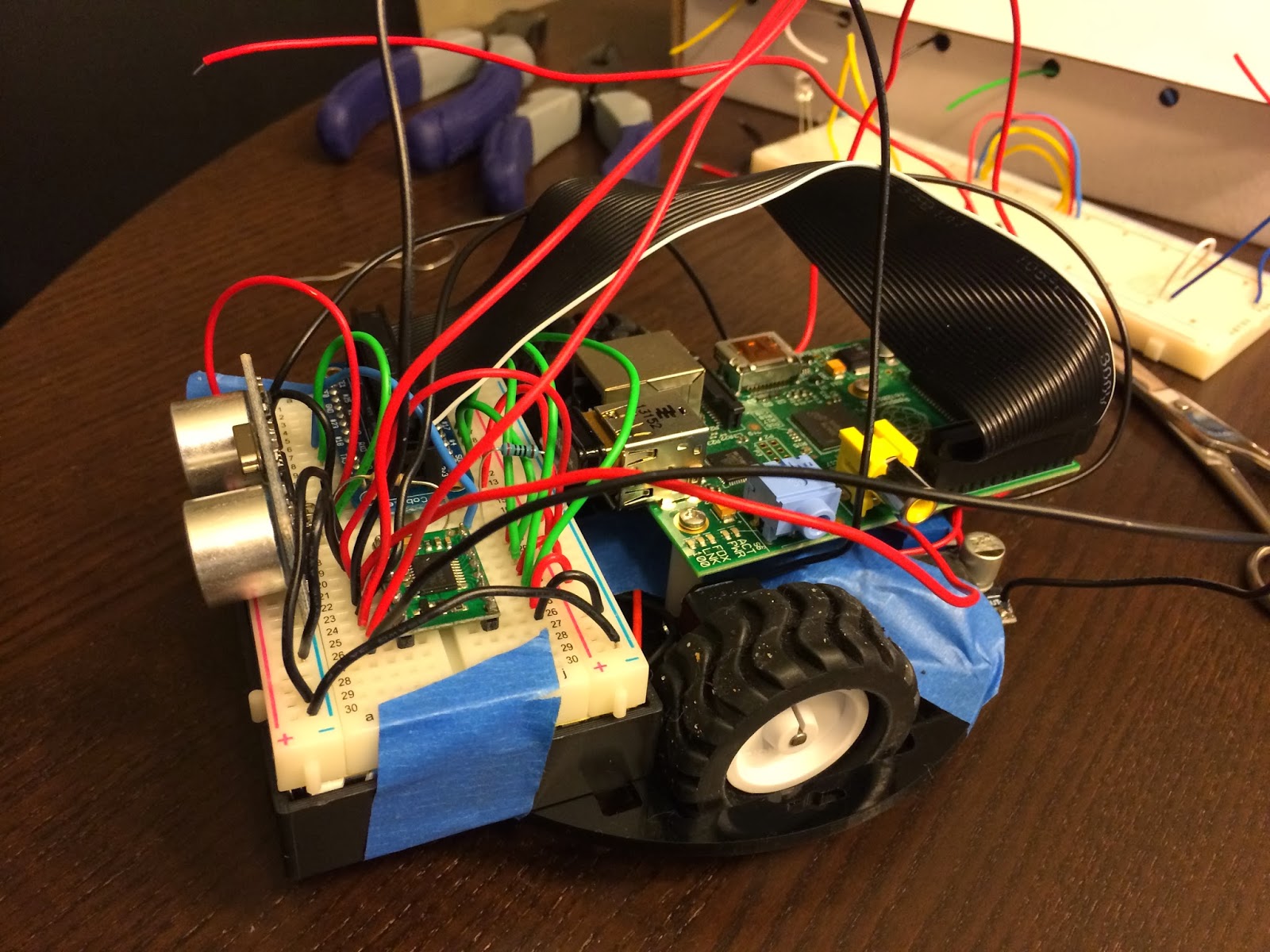
This is a summary of what I did to build the robot below. It's uses a Raspberry Pi for the micro controller and a variety of "cheap" pieces of electronics found all over the internet. There are quite a few robot kits out there, but I wanted to pick each piece myself so I could really understand the process. As a result, I've learned a lot and hope to share my gotchas.
Without further ado, I present Basil! A basic avoidance robot:

Hardware
Controllers
- 1 x RASPBERRY PI MODEL B 756-8308 Raspberry Pi B = 40.19
- 1 x #713 TB6612FNG Dual Motor Driver Carrier = 4.95
- 1 x RASPBERRY PI MODEL B 756-8308 Raspberry Pi B = 40.19
- 1 x #713 TB6612FNG Dual Motor Driver Carrier = 4.95
Sensor
Motors
- 2 x #992 100:1 Micro Metal Gearmotor = 31.90
- 1 x #1090 Pololu Wheel 42x19mm Pair = 6.98
Chassis
Power
Power
Miscellaneous
- 1 x 200 ohm resistor = basically free
- 1 x 400 ohm resistor = basically free
- 2 x Miniature Slide Switch = 2.58
- 1 x BB400 Solderless Plug-in BreadBoard = 4.40
- 1 x Adafruit Pi Cobbler Breakout Kit for Raspberry Pi = 13.99
- many wires
Wiring
I chose to wire everything on a 400 tie-point breadboard because I needed to mount the HC-SR04 sensor and didn't want to fork out mo' money for the mount. Also, the breadboard provides for easy prototyping without having to solder all the connections. Finally, the breadboard conveniently sits right on top of the 6-AA battery holder!
Here's the wiring diagram, using Fritzing:

What's not shown here is the wiring from the 6xAA battery pack to two LM2596 Voltage step down modules which step down the voltage from 7.2V to 5.0V and 6.0V for the Raspberry Pi and motors, respectively.
The other interesting piece is the resistors in series connecting the HC-SR04's echo pin to ground. Since the HC-SR04 is powered by 5V, its waveform back to the Raspberry Pi will have an amplitude of 5V. This is too high input voltage for the Pi's GPIO pin. So GPIO23 is connected between a 400Ω and 200Ω resistor. In the diagram above, the order is Signal -> 200Ω resistor -> (GPIO23 is connected here) -> 400Ω resistor -> GND. The 200Ω resistor drops the 5V source by 1.33V, so it's voltage is exactly 3.33V when measured by the GPIO23 pin. This is commonly called a voltage divider.
Code
The code is divided into 3 major parts:
- RobotBrain.py: which contains the high-level logic for moving around
- HCSR04.py: the sensor, which should really be called "Sensor.py" to abstract from the actual hardware I used
- MotorDriver.py: the driver for the motor controller (i.e. TB6612FNG)
Video
Sunday, February 2, 2014
Using the HC-SR04 ultrasonic sensor with the Raspberry Pi
This chip returns a range (at $5.49 on Amazon Prime):
Vivotech Hc-sr04 Arduino Ultrasonic Distance Measuring Sensor

and the data sheet.
With a bit of wiring and coding, I've been able to hook this up to my Raspberry Pi. A couple gotchas in case yours isn't working for you:
Vivotech Hc-sr04 Arduino Ultrasonic Distance Measuring Sensor
and the data sheet.
With a bit of wiring and coding, I've been able to hook this up to my Raspberry Pi. A couple gotchas in case yours isn't working for you:
- Make sure you're powering it with 5V. Turns out that running off the 5V GPIO pin, it was actually only supplying ~4.8V! When I switched to a voltage converter that exactly supplied 5V I was at least getting a signal back in the echo pin.
- The RPi is not a real time system. It can miss the echo edge rises and falls! This is why my python code uses while loops (below) instead of GPIO.wait_for_edge(...).
- Make sure you have a logic analyzer. I would have saved hours of debugging had I had a logic analyzer to tell me that I was getting the right waveform in the echo pin.
- Since this is a sensor, start with having it point faraway, this will give your RPi as much time as necessary to catch the echo signal. As mentioned above, if the waveform is too short, the RPi will miss the falling edge when using GPIO.wait_for_edge(...) !
Here's the code (also here: https://github.com/gfxblit/mylatestmoneysink/blob/master/HCSR04.py)
#!/usr/bin/python

import RPi.GPIO as GPIO
import time

class HCSR04:

    def __init__(self, triggerPin, echoPin):
        GPIO.setmode(GPIO.BCM)
        self._triggerPin = triggerPin;
        self._echoPin = echoPin
        GPIO.setup(self._triggerPin, GPIO.OUT)
        GPIO.setup(self._echoPin, GPIO.IN)
 GPIO.output(self._triggerPin, GPIO.LOW)

    def getRangeInCentimeters(self):
        # issue a 10uS pulse
        GPIO.output(self._triggerPin, GPIO.HIGH)
 time.sleep(0.00001)
        GPIO.output(self._triggerPin, GPIO.LOW)

        # wait for the echo
        while GPIO.input(self._echoPin) == 0:
            start = time.time()

        while GPIO.input(self._echoPin) == 1:
            stop = time.time()

        return (stop - start)  * 1000000.0 / 58.0;

    def __del__(self):
        GPIO.cleanup()


if __name__ == "__main__":
    hcsr04 = HCSR04(17, 4)
    raw_input("waiting to start")
    while 1:
        print "range: " + str(hcsr04.getRangeInCentimeters())
        time.sleep(1)
Thursday, January 23, 2014
A prototyping board to mount onto the Raspberry Pi...
Humble Pi also looks promising and it's on Amazon prime for $10.80!
http://www.amazon.com/Humble-Pi-Kit-Raspberry/dp/B00C45IMH2
I'm also considering this PCB:
https://www.tindie.com/products/DTronixs/piio-pri-protoboard-for-raspberry-pi-pcb-only/ (only $7.50!). We'll see how the Humble Pi works out first though, since I just put in an order for it.
1/24/14 Update: correction, the Humble Pi is a prototyping board not a breadboard!
http://www.raspians.com/Knowledgebase/2prototyping-plates-and-project-kits-for-the-pi/ has a great description of boards.
Wednesday, January 22, 2014
Driving the 1:100 motors with the TB6612FNG driver carrier and LM2596S step down converter
Here's what the TB6612FNG looks like from the top, annotated with the pin names (taken from http://www.embeddedrelated.com/showarticle/498.php):


Left side
- GND - Microcontroller ground
- VCC - VCC from microcontroller (2.7V-5.5V)
- AO1 - Output to (-) lead of motor A
- AO2 - Output to (+) lead of motor A
- BO2 - Output to (+) lead of motor B
- BO1 - Output to (-) lead of motor B
- VMOT - positive pole of motor battery
- GND - negative pole of motor battery
Right side
- PWMA - PWM pin on microcontroller
- AIN2 - digital pin on microcontroller
- AIN1 - digital pin on microcontroller
- STBY - digital pin on microcontroller, or tie to VCC
- BIN1 - digital pin on microcontroller
- BIN2 - digital pin on microcontroller
- PWMB - PWM pin on microcontroller
- GND - GND of micro controller
For my RPi, I hooked up
- GPIO2 - AIN1 (yellow)
- GPIO3 - AIN2 (yellow)
- GPIO4 - BIN1 (blue)
- GPIO17 - BIN2 (blue)
- VCC - PWMA/B (green)
- VCC - STBY (red)
Here's a picture of the wiring:

Note I have the LM2596S step down voltage converter on the bottom, to convert from the ~7.2V to 6 for the DC motors.
Here is the python code to drive it: https://github.com/gfxblit/mylatestmoneysink/blob/master/MotorDriver.py
Monday, January 20, 2014
Problems with the chassis!
Just my luck! The RPi doesn't have mounting holes that fit the Pololu 5" Robot Chassis RRC04A!

I'll need to think of a creative solution...plus where to fit the battery pack?
1/21/14 Update: I think I can mount the RPi as follows:


I'll need to think of a creative solution...plus where to fit the battery pack?
1/21/14 Update: I think I can mount the RPi as follows:
It's going to be a little crooked but I don't think it will be noticeable. Next, I'll think about where the battery pack should go. Maybe I need to a 3x2 configuration instead of the 6x1 I bought.
Actually, the battery pack should fit here! (shown in green)

Actually, the battery pack should fit here! (shown in green)
Total current usage
What I've been thinking about lately is current. I ordered a 6-AA battery holder, which means I have about 6 Ah using NiMH batteries , according to http://www.allaboutbatteries.com/Energy-tables.html.
I'm assuming the RPi draws 1A and the 2 dc motors will draw a total of 2.4A (from the TB6612FNG spec: http://www.pololu.com/file/0J86/TB6612FNG.pdf). This means I have a total of 3.4A with everything turned on.
This graph from http://www.powerstream.com/AA-tests.htm shows that at about 3.4 A, I should have somewhere between 1.0 to 1.25V.
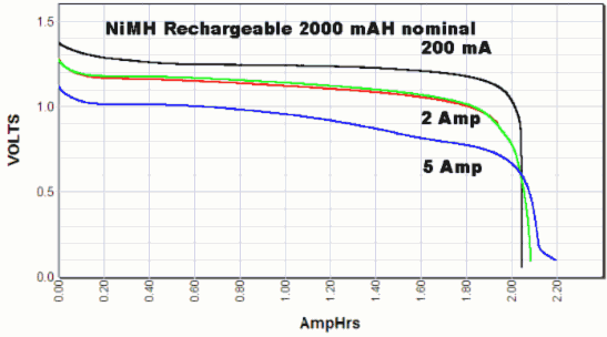
With the voltage step down converter I bought, the LM2596, I'm hoping it can keep the voltage at ~5V to power my RPi.
This is nice youtube video testing the LM2596:
I'm assuming the RPi draws 1A and the 2 dc motors will draw a total of 2.4A (from the TB6612FNG spec: http://www.pololu.com/file/0J86/TB6612FNG.pdf). This means I have a total of 3.4A with everything turned on.
This graph from http://www.powerstream.com/AA-tests.htm shows that at about 3.4 A, I should have somewhere between 1.0 to 1.25V.
With the voltage step down converter I bought, the LM2596, I'm hoping it can keep the voltage at ~5V to power my RPi.
This is nice youtube video testing the LM2596:
Update: on the LM2596 spec, it says it can supply up to 3 A reliably:
This means I'll have to run 2 of these, one for the RPi, the other for the motors.
Getting started on the my autonomous robot
After a couple weeks of tinkering with my Raspberry Pi and wondering what to do with it, I've finally decided to build an autonomous robot.
After several days of browsing sparkfun.com and amazon.com, I've finally converged on a basic foundation:
Chasis
1 x #989 Pololu Micro Metal Gearmotor Bracket Pair - Black = 4.99
1 x #951 Pololu Ball Caster with 3/8" Metal Ball = 1.99
1 x #1501 Pololu 5" Robot Chassis RRC04A Solid Black = 7.95
1/22/14 Update: I just purchased another LM2596 step down for the RPi. The first one works great to step down from ~7.2V to 6.0V needed for the 100:1 gear motors.
After several days of browsing sparkfun.com and amazon.com, I've finally converged on a basic foundation:
Chasis
1 x #989 Pololu Micro Metal Gearmotor Bracket Pair - Black = 4.99
1 x #951 Pololu Ball Caster with 3/8" Metal Ball = 1.99
1 x #1501 Pololu 5" Robot Chassis RRC04A Solid Black = 7.95
Motor
2 x #992 100:1 Micro Metal Gearmotor = 31.90
Wheels
1 x #1090 Pololu Wheel 42x19mm Pair = 6.98
Battery
1 x #1155 6-AA Battery Holder = 1.75
Electronics
1 x #713 TB6612FNG Dual Motor Driver Carrier = 4.95
2 x RioRand LM2596 DC-DC Buck Converter Step Down Module Power Supply Output 1.23V-30V (1 Pcs-LM2596) = 8.00
Note those motors are the most expensive piece!!!
The idea is to build a small robot first, have it navigate on a table. I have yet to decide on what sensors to add (leaning towards camera). Also, still need to decide on how to power it, and mount it on the chasis.
1/22/14 Update: I just purchased another LM2596 step down for the RPi. The first one works great to step down from ~7.2V to 6.0V needed for the 100:1 gear motors.
Subscribe to:
Posts (Atom)