Introduction
This is a summary of what I did to build the robot below. It's uses a Raspberry Pi for the micro controller and a variety of "cheap" pieces of electronics found all over the internet. There are quite a few robot kits out there, but I wanted to pick each piece myself so I could really understand the process. As a result, I've learned a lot and hope to share my gotchas.
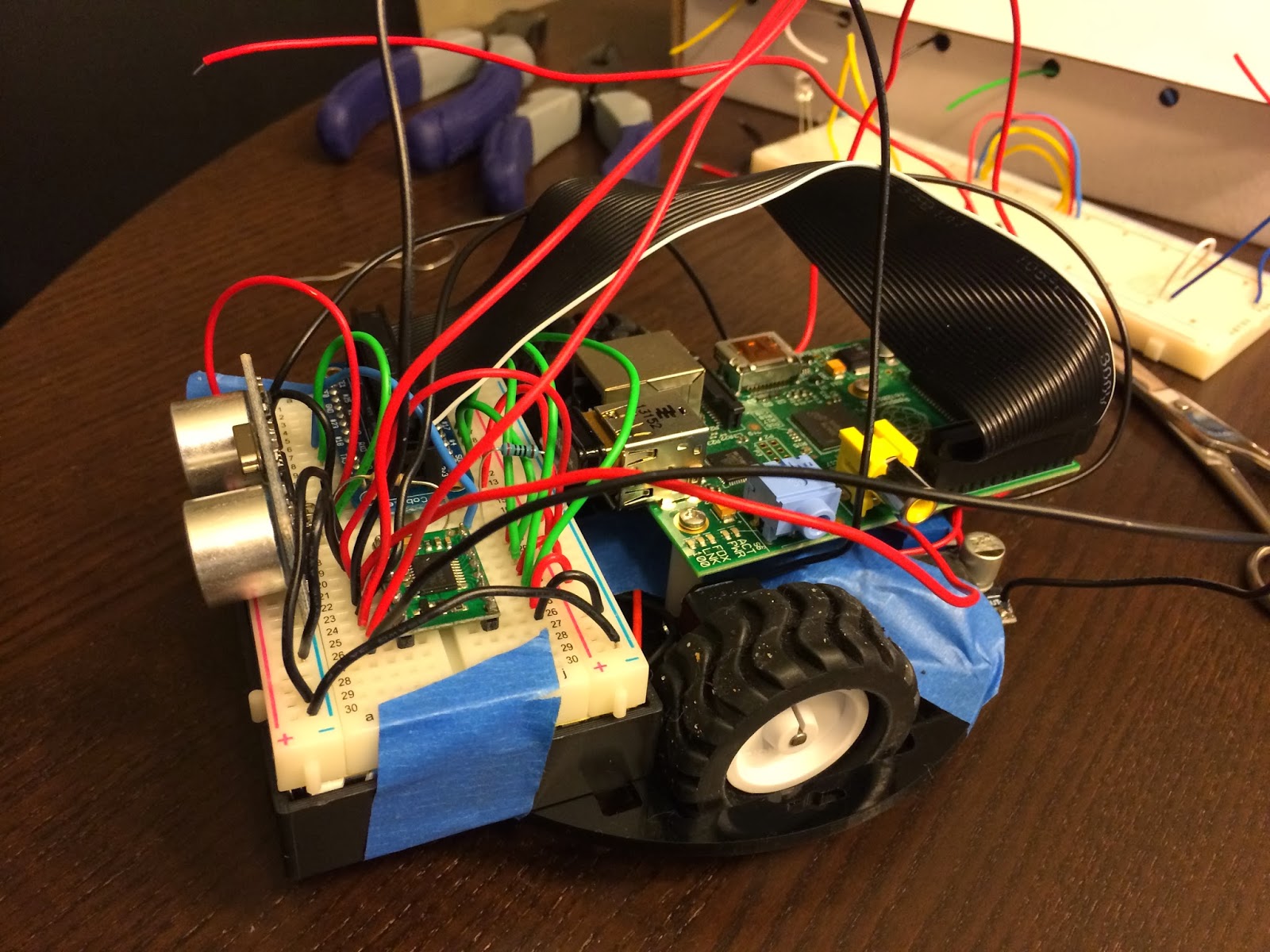
Without further ado, I present Basil! A basic avoidance robot:

Hardware
Controllers
- 1 x RASPBERRY PI MODEL B 756-8308 Raspberry Pi B = 40.19
- 1 x #713 TB6612FNG Dual Motor Driver Carrier = 4.95
- 1 x RASPBERRY PI MODEL B 756-8308 Raspberry Pi B = 40.19
- 1 x #713 TB6612FNG Dual Motor Driver Carrier = 4.95
Sensor
Motors
- 2 x #992 100:1 Micro Metal Gearmotor = 31.90
- 1 x #1090 Pololu Wheel 42x19mm Pair = 6.98
Chassis
Power
Power
Miscellaneous
- 1 x 200 ohm resistor = basically free
- 1 x 400 ohm resistor = basically free
- 2 x Miniature Slide Switch = 2.58
- 1 x BB400 Solderless Plug-in BreadBoard = 4.40
- 1 x Adafruit Pi Cobbler Breakout Kit for Raspberry Pi = 13.99
- many wires
Wiring
I chose to wire everything on a 400 tie-point breadboard because I needed to mount the HC-SR04 sensor and didn't want to fork out mo' money for the mount. Also, the breadboard provides for easy prototyping without having to solder all the connections. Finally, the breadboard conveniently sits right on top of the 6-AA battery holder!
Here's the wiring diagram, using Fritzing:

What's not shown here is the wiring from the 6xAA battery pack to two LM2596 Voltage step down modules which step down the voltage from 7.2V to 5.0V and 6.0V for the Raspberry Pi and motors, respectively.
The other interesting piece is the resistors in series connecting the HC-SR04's echo pin to ground. Since the HC-SR04 is powered by 5V, its waveform back to the Raspberry Pi will have an amplitude of 5V. This is too high input voltage for the Pi's GPIO pin. So GPIO23 is connected between a 400Ω and 200Ω resistor. In the diagram above, the order is Signal -> 200Ω resistor -> (GPIO23 is connected here) -> 400Ω resistor -> GND. The 200Ω resistor drops the 5V source by 1.33V, so it's voltage is exactly 3.33V when measured by the GPIO23 pin. This is commonly called a voltage divider.
Code
The code is divided into 3 major parts:
- RobotBrain.py: which contains the high-level logic for moving around
- HCSR04.py: the sensor, which should really be called "Sensor.py" to abstract from the actual hardware I used
- MotorDriver.py: the driver for the motor controller (i.e. TB6612FNG)
No comments:
Post a Comment