Sunday, April 6, 2014

Building a Raspberry Pi-based Robot

Introduction

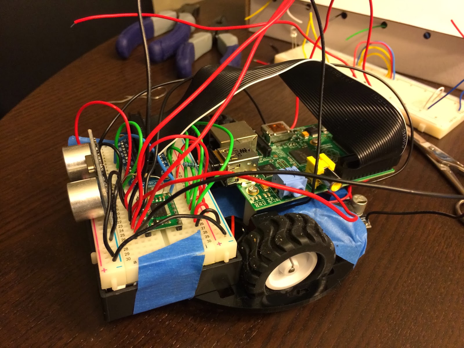
This is a summary of what I did to build the robot below. It's uses a Raspberry Pi for the micro controller and a variety of "cheap" pieces of electronics found all over the internet. There are quite a few robot kits out there, but I wanted to pick each piece myself so I could really understand the process. As a result, I've learned a lot and hope to share my gotchas.

Without further ado, I present Basil! A basic avoidance robot:

Hardware

Controllers

Sensor

Motors


Chassis

Miscellaneous

Wiring

I chose to wire everything on a 400 tie-point breadboard because I needed to mount the HC-SR04 sensor and didn't want to fork out mo' money for the mount. Also, the breadboard provides for easy prototyping without having to solder all the connections. Finally, the breadboard conveniently sits right on top of the 6-AA battery holder!

Here's the wiring diagram, using Fritzing:

What's not shown here is the wiring from the 6xAA battery pack to two LM2596 Voltage step down modules which step down the voltage from 7.2V to 5.0V and 6.0V for the Raspberry Pi and motors, respectively.

The other interesting piece is the resistors in series connecting the HC-SR04's echo pin to ground. Since the HC-SR04 is powered by 5V, its waveform back to the Raspberry Pi will have an amplitude of 5V. This is too high input voltage for the Pi's GPIO pin. So GPIO23 is connected between a 400Ω and 200Ω resistor. In the diagram above, the order is Signal -> 200Ω resistor -> (GPIO23 is connected here) -> 400Ω resistor -> GND. The 200Ω resistor drops the 5V source by 1.33V, so it's voltage is exactly 3.33V when measured by the GPIO23 pin. This is commonly called a voltage divider.

Code

The code is divided into 3 major parts:
  • RobotBrain.py: which contains the high-level logic for moving around
  • HCSR04.py: the sensor, which should really be called "Sensor.py" to abstract from the actual hardware I used
  • MotorDriver.py: the driver for the motor controller (i.e. TB6612FNG)

Video


Sunday, February 2, 2014

Using the HC-SR04 ultrasonic sensor with the Raspberry Pi

This chip returns a range (at $5.49 on Amazon Prime):
Vivotech Hc-sr04 Arduino Ultrasonic Distance Measuring Sensor

and the data sheet.

With a bit of wiring and coding, I've been able to hook this up to my Raspberry Pi. A couple gotchas in case yours isn't working for you:

  • Make sure you're powering it with 5V.  Turns out that running off the 5V GPIO pin, it was actually only supplying ~4.8V! When I switched to a voltage converter that exactly supplied 5V I was at least getting a signal back in the echo pin.
  • The RPi is not a real time system. It can miss the echo edge rises and falls! This is why my python code uses while loops (below) instead of GPIO.wait_for_edge(...).
  • Make sure you have a logic analyzer. I would have saved hours of debugging had I had a logic analyzer to tell me that I was getting the right waveform in the echo pin.
  • Since this is a sensor, start with having it point faraway, this will give your RPi as much time as  necessary to catch the echo signal. As mentioned above, if the waveform is too short, the RPi will miss the falling edge when using GPIO.wait_for_edge(...) !
#!/usr/bin/python

import RPi.GPIO as GPIO
import time

class HCSR04:

    def __init__(self, triggerPin, echoPin):
        GPIO.setmode(GPIO.BCM)
        self._triggerPin = triggerPin;
        self._echoPin = echoPin
        GPIO.setup(self._triggerPin, GPIO.OUT)
        GPIO.setup(self._echoPin, GPIO.IN)
 GPIO.output(self._triggerPin, GPIO.LOW)

    def getRangeInCentimeters(self):
        # issue a 10uS pulse
        GPIO.output(self._triggerPin, GPIO.HIGH)
 time.sleep(0.00001)
        GPIO.output(self._triggerPin, GPIO.LOW)
        
        # wait for the echo
        while GPIO.input(self._echoPin) == 0:
            start = time.time()

        while GPIO.input(self._echoPin) == 1:
            stop = time.time()
        
        return (stop - start)  * 1000000.0 / 58.0;
         
    def __del__(self):
        GPIO.cleanup()
    
 
if __name__ == "__main__":
    hcsr04 = HCSR04(17, 4)
    raw_input("waiting to start")
    while 1:
        print "range: " + str(hcsr04.getRangeInCentimeters())
        time.sleep(1)

Thursday, January 23, 2014

A prototyping board to mount onto the Raspberry Pi...

Humble Pi also looks promising and it's on Amazon prime for $10.80!
http://www.amazon.com/Humble-Pi-Kit-Raspberry/dp/B00C45IMH2
I'm also considering this PCB:
 https://www.tindie.com/products/DTronixs/piio-pri-protoboard-for-raspberry-pi-pcb-only/ (only $7.50!). We'll see how the Humble Pi works out first though, since I just put in an order for it.

1/24/14 Update: correction, the Humble Pi is a prototyping board not a breadboard!
http://www.raspians.com/Knowledgebase/2prototyping-plates-and-project-kits-for-the-pi/ has a great description of boards. 

Wednesday, January 22, 2014

Driving the 1:100 motors with the TB6612FNG driver carrier and LM2596S step down converter


Here's what the TB6612FNG looks like from the top, annotated with the pin names (taken from http://www.embeddedrelated.com/showarticle/498.php):

TB6612FNG motor driver
Left side
  • GND - Microcontroller ground
  • VCC - VCC from microcontroller (2.7V-5.5V)
  • AO1 - Output to (-) lead of motor A
  • AO2 - Output to (+) lead of motor A
  • BO2 - Output to (+) lead of motor B
  • BO1 - Output to (-) lead of motor B
  • VMOT - positive pole of motor battery
  • GND - negative pole of motor battery
Right side
  • PWMA - PWM pin on microcontroller
  • AIN2 - digital pin on microcontroller
  • AIN1 - digital pin on microcontroller
  • STBY - digital pin on microcontroller, or tie to VCC
  • BIN1 - digital pin on microcontroller
  • BIN2 - digital pin on microcontroller
  • PWMB - PWM pin on microcontroller
  • GND - GND of micro controller
For my RPi, I hooked up
  • GPIO2 - AIN1 (yellow)
  • GPIO3 - AIN2 (yellow)
  • GPIO4 - BIN1 (blue)
  • GPIO17 - BIN2 (blue)
  • VCC - PWMA/B (green)
  • VCC - STBY (red)
Here's a picture of the wiring:

Note I have the LM2596S step down voltage converter on the bottom, to convert from the ~7.2V to 6 for the DC motors.


Monday, January 20, 2014

Problems with the chassis!

Just my luck! The RPi doesn't have mounting holes that fit the Pololu 5" Robot Chassis RRC04A!

I'll need to think of a creative solution...plus where to fit the battery pack?


1/21/14 Update: I think I can mount the RPi as follows:

It's going to be a little crooked but I don't think it will be noticeable. Next, I'll think about where the battery pack should go. Maybe I need to a 3x2 configuration instead of the 6x1 I bought.

Actually, the battery pack should fit here! (shown in green)


Total current usage

What I've been thinking about lately is current. I ordered a 6-AA battery holder, which means I have about 6 Ah using NiMH batteries , according to http://www.allaboutbatteries.com/Energy-tables.html.

I'm assuming the RPi draws 1A and the 2 dc motors will draw a total of 2.4A (from the TB6612FNG spec: http://www.pololu.com/file/0J86/TB6612FNG.pdf). This means I have a total of 3.4A with everything turned on.

This graph from http://www.powerstream.com/AA-tests.htm shows that at about 3.4 A, I should have somewhere between 1.0 to 1.25V.
NiMH AA cell voltage during discharge at  200mA discharge current

With the voltage step down converter I bought, the LM2596, I'm hoping it can keep the voltage at ~5V to power my RPi.

This is nice youtube video testing the LM2596:


Update: on the LM2596 spec, it says it can supply up to 3 A reliably: 
This means I'll have to run 2 of these, one for the RPi, the other for the motors. 

Getting started on the my autonomous robot

After a couple weeks of tinkering with my Raspberry Pi and wondering what to do with it, I've finally decided to build an autonomous robot.

After several days of browsing sparkfun.com and amazon.com, I've finally converged on a basic foundation:

Chasis
  1 x #989 Pololu Micro Metal Gearmotor Bracket Pair - Black = 4.99
  1 x #951 Pololu Ball Caster with 3/8" Metal Ball = 1.99
  1 x #1501 Pololu 5" Robot Chassis RRC04A Solid Black = 7.95

Motor

Wheels
  1 x #1090 Pololu Wheel 42x19mm Pair = 6.98

Battery

Electronics

Note those motors are the most expensive piece!!!

The idea is to build a small robot first, have it navigate on a table. I have yet to decide on what sensors to add (leaning towards camera). Also, still need to decide on how to power it, and mount it on the chasis.

1/22/14 Update: I just purchased another LM2596 step down for the RPi. The first one works great to step down from ~7.2V to 6.0V needed for the 100:1 gear motors.