Thursday, January 23, 2014

A prototyping board to mount onto the Raspberry Pi...

Humble Pi also looks promising and it's on Amazon prime for $10.80!
http://www.amazon.com/Humble-Pi-Kit-Raspberry/dp/B00C45IMH2
I'm also considering this PCB:
 https://www.tindie.com/products/DTronixs/piio-pri-protoboard-for-raspberry-pi-pcb-only/ (only $7.50!). We'll see how the Humble Pi works out first though, since I just put in an order for it.

1/24/14 Update: correction, the Humble Pi is a prototyping board not a breadboard!
http://www.raspians.com/Knowledgebase/2prototyping-plates-and-project-kits-for-the-pi/ has a great description of boards. 

Wednesday, January 22, 2014

Driving the 1:100 motors with the TB6612FNG driver carrier and LM2596S step down converter


Here's what the TB6612FNG looks like from the top, annotated with the pin names (taken from http://www.embeddedrelated.com/showarticle/498.php):

TB6612FNG motor driver
Left side
  • GND - Microcontroller ground
  • VCC - VCC from microcontroller (2.7V-5.5V)
  • AO1 - Output to (-) lead of motor A
  • AO2 - Output to (+) lead of motor A
  • BO2 - Output to (+) lead of motor B
  • BO1 - Output to (-) lead of motor B
  • VMOT - positive pole of motor battery
  • GND - negative pole of motor battery
Right side
  • PWMA - PWM pin on microcontroller
  • AIN2 - digital pin on microcontroller
  • AIN1 - digital pin on microcontroller
  • STBY - digital pin on microcontroller, or tie to VCC
  • BIN1 - digital pin on microcontroller
  • BIN2 - digital pin on microcontroller
  • PWMB - PWM pin on microcontroller
  • GND - GND of micro controller
For my RPi, I hooked up
  • GPIO2 - AIN1 (yellow)
  • GPIO3 - AIN2 (yellow)
  • GPIO4 - BIN1 (blue)
  • GPIO17 - BIN2 (blue)
  • VCC - PWMA/B (green)
  • VCC - STBY (red)
Here's a picture of the wiring:

Note I have the LM2596S step down voltage converter on the bottom, to convert from the ~7.2V to 6 for the DC motors.


Monday, January 20, 2014

Problems with the chassis!

Just my luck! The RPi doesn't have mounting holes that fit the Pololu 5" Robot Chassis RRC04A!

I'll need to think of a creative solution...plus where to fit the battery pack?


1/21/14 Update: I think I can mount the RPi as follows:

It's going to be a little crooked but I don't think it will be noticeable. Next, I'll think about where the battery pack should go. Maybe I need to a 3x2 configuration instead of the 6x1 I bought.

Actually, the battery pack should fit here! (shown in green)


Total current usage

What I've been thinking about lately is current. I ordered a 6-AA battery holder, which means I have about 6 Ah using NiMH batteries , according to http://www.allaboutbatteries.com/Energy-tables.html.

I'm assuming the RPi draws 1A and the 2 dc motors will draw a total of 2.4A (from the TB6612FNG spec: http://www.pololu.com/file/0J86/TB6612FNG.pdf). This means I have a total of 3.4A with everything turned on.

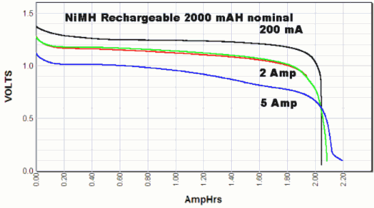
This graph from http://www.powerstream.com/AA-tests.htm shows that at about 3.4 A, I should have somewhere between 1.0 to 1.25V.
NiMH AA cell voltage during discharge at  200mA discharge current

With the voltage step down converter I bought, the LM2596, I'm hoping it can keep the voltage at ~5V to power my RPi.

This is nice youtube video testing the LM2596:


Update: on the LM2596 spec, it says it can supply up to 3 A reliably: 
This means I'll have to run 2 of these, one for the RPi, the other for the motors. 

Getting started on the my autonomous robot

After a couple weeks of tinkering with my Raspberry Pi and wondering what to do with it, I've finally decided to build an autonomous robot.

After several days of browsing sparkfun.com and amazon.com, I've finally converged on a basic foundation:

Chasis
  1 x #989 Pololu Micro Metal Gearmotor Bracket Pair - Black = 4.99
  1 x #951 Pololu Ball Caster with 3/8" Metal Ball = 1.99
  1 x #1501 Pololu 5" Robot Chassis RRC04A Solid Black = 7.95

Motor

Wheels
  1 x #1090 Pololu Wheel 42x19mm Pair = 6.98

Battery

Electronics

Note those motors are the most expensive piece!!!

The idea is to build a small robot first, have it navigate on a table. I have yet to decide on what sensors to add (leaning towards camera). Also, still need to decide on how to power it, and mount it on the chasis.

1/22/14 Update: I just purchased another LM2596 step down for the RPi. The first one works great to step down from ~7.2V to 6.0V needed for the 100:1 gear motors.